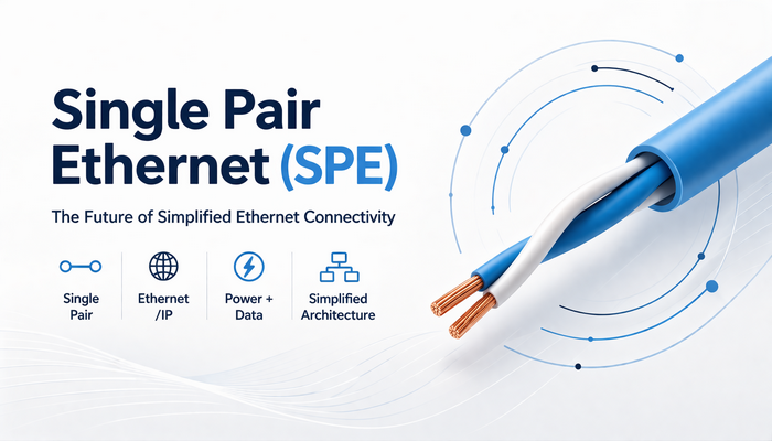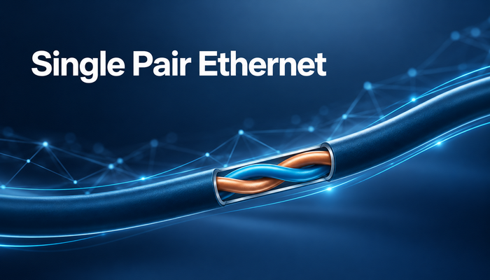
Single Pair Ethernet (SPE) is a family of Ethernet physical-layer technologies that carries data over a single balanced pair of copper conductors. It extends Ethernet connectivity to sensors, actuators and other field devices while creating opportunities to simplify cabling.
For industrial and building applications that need long reach and moderate bandwidth, 10BASE-T1L is particularly relevant. It provides 10 Mbps full-duplex, point-to-point communication over links of up to approximately 1,000 meters when the complete link meets the required electrical specifications. Its value lies in bringing field devices into a common Ethernet infrastructure. [1]
SPE describes a technology family; 10BASE-T1L is one member. Data rate, reach and topology depend on the specific physical layer. Selecting a product therefore starts with identifying which SPE technology it implements. [1, 2]
Technology | Data rate | Main characteristics |
10BASE-T1L | 10 Mbps | Long-reach, full-duplex, point-to-point links for field connectivity. |
10BASE-T1S | 10 Mbps | Short-reach links, including shared-medium multidrop configurations. |
100BASE-T1 | 100 Mbps | Shorter-reach links used in automotive and related embedded applications. |
1000BASE-T1 | 1 Gbps | Higher-bandwidth single-pair links; verify the applicable reach and channel requirements. |
SPE does not always mean 10 Mbps or 1,000-meter reach. Those specifications must be associated with the relevant physical-layer standard and link conditions.
10BASE-T1L changes how Ethernet signals travel across the physical link. Ethernet frames and the network protocols they carry can still be used, allowing compatible field devices to participate in IP-based systems.
Physical connectivity alone does not convert an application protocol. Connecting an RS-485 device to an SPE interface does not turn Modbus RTU into Ethernet. A suitable protocol gateway or an upgraded device is still required.
10BASE-T1L uses three-level pulse amplitude modulation (PAM3) with 4B3T coding at a symbol rate of 7.5 MBd to carry 10 Mbps data. Both endpoints transmit and receive over the same pair simultaneously. Echo cancellation helps the receiver distinguish the incoming signal from its own transmitted signal. [1, 3]
The technology supports 1.0 Vpp and 2.4 Vpp transmit amplitude modes. The permitted channel loss depends on the operating mode. Achievable distance is determined by the electrical performance of the entire link, rather than cable length alone. [1, 3]
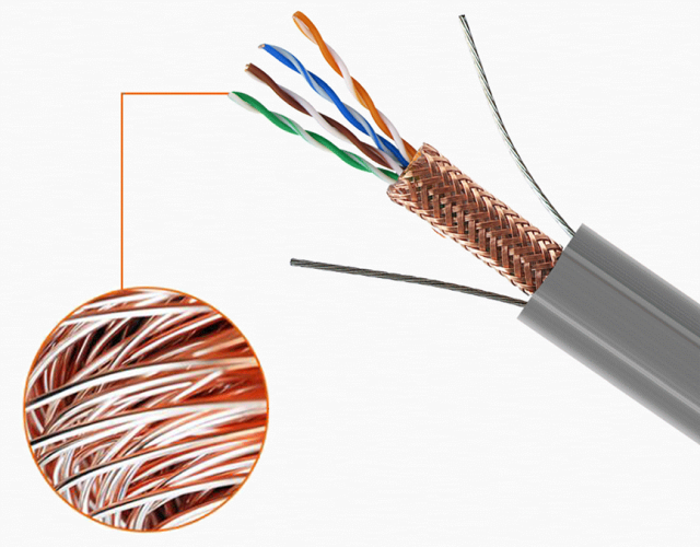
A single pair is a balanced transmission path, typically implemented with suitable twisted-pair cable. Insertion loss, return loss, balance, connector quality and the electromagnetic environment all affect performance. Existing two-conductor cabling may be reusable, but continuity alone does not establish SPE suitability or guarantee maximum reach. [4]
Using one conductor pair reduces the number of pairs needed for the data connection and supports compact interfaces. This can be valuable where installation space or cable routing is constrained. Total project cost still depends on converters, switches, power supplies, installation and testing; conductor count alone does not establish the savings.
10BASE-T1L offers a long-reach copper Ethernet path to sensors, controllers and monitoring devices located far from a network cabinet. In suitable installations, this can reduce the need for intermediate active equipment and the local power and maintenance access that equipment requires. [1, 3]
Compatible Power over Data Line (PoDL) or Single-pair Power over Ethernet (SPoE) implementations can carry DC power alongside data. This requires appropriate power sourcing equipment, powered devices and coupling circuitry. Remote power is an optional system capability, not an automatic feature of every SPE product. [5]
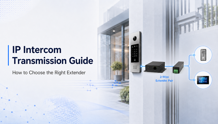
SPE-side power must also be distinguished from conventional RJ45 PoE under IEEE 802.3af/at/bt. To power a standard PoE camera or intercom, the remote converter needs a compatible PoE output. SPE power support alone does not establish compatibility with the terminal device.
Some 10BASE-T1L PHYs provide time-domain reflectometry (TDR), link quality monitoring and loopback tests. These functions can help identify cable faults and assess link health. Whether maintenance staff can use them depends on the finished product hardware, firmware and management interface. A chip capability is not necessarily an exposed product feature. [6]
Application | Potential value | What to verify |
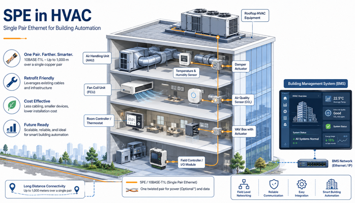
Building automation and HVAC | Ethernet access for distributed monitoring and control devices. | Application protocols, reach, power and cabling. |
Industrial condition monitoring | Connectivity for sensors and edge acquisition devices. | Traffic volume, EMC, temperature and diagnostics. |
Process automation | Ethernet connectivity to field instruments. | Ethernet-APL requirements, intrinsic safety and certification. |
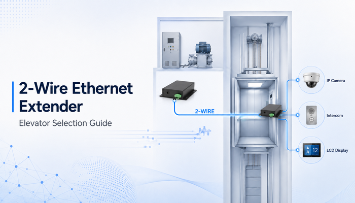
Elevator auxiliary communication | Links for displays, intercoms, monitoring and selected video services. | Traveling cable, motion reliability, bandwidth and endpoint power. |
Existing infrastructure upgrades | Potential reuse of qualified installed cable pairs. | Channel performance, connectors, topology and load testing. |
Ethernet-APL and 10BASE-T1L are related, but the terms are not interchangeable. Ethernet-APL adds system and installation requirements for process-industry applications. A standard 10BASE-T1L product is not automatically APL-compliant or suitable for hazardous locations. [4]
Moving installations need particular attention to connection reliability. In a 2024 Embedded World paper, Brunner and Ostertag reported that a single-contact interruption as short as 750 microseconds could cause link loss in their tested configurations. Measured recovery times ranged from 400 milliseconds to 3 seconds. These results are specific to the test setup, but demonstrate why connector and moving-cable validation matters. [7]
The nominal link rate is 10 Mbps. Application throughput is lower because of protocol overhead and implementation details. For CCTV, calculate camera count, peak bitrates and concurrent traffic. H.265 support alone does not establish whether the link has sufficient capacity.
A working data link does not guarantee adequate power at the far end. Check cable loop resistance, voltage drop, startup demand and the load minimum operating voltage. The data reach and the usable power reach must be evaluated separately.
An individual 10BASE-T1L link is point-to-point. Star or line networks require appropriate switching equipment. Multiple endpoints cannot simply be connected in parallel to one conductor pair as though it were a passive multidrop bus. [1]
Verify the physical layer, connector pinout, power method, management functions and environmental ratings. SPE and Ethernet-over-two-wire products based on other physical layers are not directly interoperable simply because both use two conductors.
As more field devices become Ethernet-connected, project requirements may increasingly include link diagnostics, asset visibility and maintenance efficiency. Existing PHY diagnostic tools provide a technical foundation, while the practical benefit depends on how equipment and software expose those capabilities. [6]
The standards landscape extends beyond 10 Mbps. IEEE 802.3dg-2026 was published on June 23, 2026, adding physical-layer specifications for 100 Mbps operation and associated optional power delivery over a single balanced pair of conductors. [8]
This expands the standards foundation for applications requiring more bandwidth. Publication does not establish the availability of every product type, nor does it mean installed 10BASE-T1L hardware can be upgraded directly to 100 Mbps.
The paper Timestamp accuracy of 10BASE-T1L for TSN applications by Brunner, Da Silva Miranda and Ostertag identifies timestamp accuracy as a research topic for time-sensitive networking. SPE alone does not guarantee deterministic latency: timestamp implementation, switching, synchronization protocols and the end-to-end network design remain important. [9]
Taken together, standards developments, cable studies and research on connection interruptions suggest that deployment will depend on complete-link validation as well as silicon performance. Multivendor interoperability, power compatibility, EMC performance and maintainability are likely to remain important selection criteria. This is an engineering assessment based on the cited material, rather than a market forecast.
SPE carries Ethernet data over a single balanced conductor pair. It uses physical-layer and interface arrangements that differ from common RJ45 copper Ethernet. Data rate and reach depend on the SPE variant.
Yes, through a suitable media converter or switch that supports both physical layers. A passive wiring adapter cannot convert a conventional RJ45 Ethernet port into a 10BASE-T1L port.
Possibly. The complete link must be checked for loss, balance, connection quality and environmental suitability. A continuity test is not enough to establish SPE performance.
No. Verify SPE-side power support separately from any standard RJ45 PoE output required by the connected terminal.
It can be evaluated for video applications with moderate bandwidth requirements. Check peak video bitrates, concurrent traffic, protocol overhead, remote power and link stability under realistic operating conditions.
Before selecting an SPE converter or switch, define the number of endpoints, application protocols, peak traffic, link distance, cable specifications and remote power demand. Use these requirements to establish a meaningful sample test.
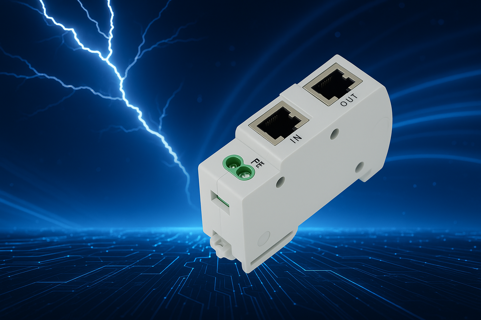
A media converter can provide a path to SPE when an installation uses existing RJ45 terminal devices. For multiple distributed endpoints, evaluate a multiport SPE switch and its total power budget.
To discuss an application with Ourten, share the cable type, distance, terminal model and power requirements. These details provide a basis for assessing the transmission approach and defining test conditions.
Click here for more Ourten SPE converter information.
[1] IEEE 802.3 Working Group. IEEE 802.3cg Tutorial. 2019.
[2] Texas Instruments. How 10BASE-T1L Single-Pair Ethernet Brings the Network Edge Closer With More Bandwidth. Technical article, SSZT247.
[3] Analog Devices. Enabling Seamless Ethernet to the Field with 10BASE-T1L Connectivity.
[4] Hector Arroyo. 10BASE-T1L Single-Pair Ethernet Cable Reach and Link Performance.
[5] Analog Devices. CN0575: 10BASE-T1L Field Device Development Platform with Class 12 and 13 SPoE.
[6] Analog Devices. AN-2553: ADIN1100/ADIN1110/ADIN2111 Link and Cable Diagnostics.
[7] Kilian Brunner and Martin Ostertag. 10BASE-T1L micro interruptions: importance of good cabling between moving parts. Embedded World Conference 2024, pp. 560–565.
[8] IEEE Standards Association. IEEE 802.3dg-2026.
[9] Kilian Brunner, Luis Da Silva Miranda and Martin Ostertag. Timestamp accuracy of 10BASE-T1L for TSN applications. 2023 IEEE Third International Conference on Signal, Control and Communication. Institutional record published in 2024. DOI: 10.1109/SCC59637.2023.10527511.